Tyrel's Blog

Code, Flying, Tech, Automation

Nov 04, 2022

Neighbor's Water Heater Automation (part 1)

The Setting

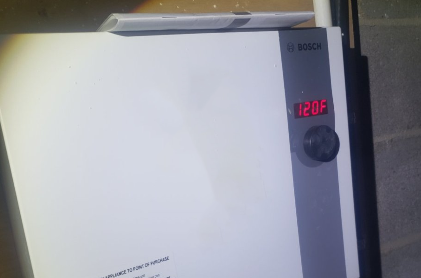
My neighbor has a Bosch tankless water heater he put in last year. This water heater has one slight problem that when the power even blips a single second, it gets set back to its lowest temperature of 95°F. My neighbor (we'll call him Frank for this post because Frank Tank is funny) Frank wants to set his heater to 120°F in his house. The problem arises in that his water heater is under the house in his crawl space.

Without an easy way to set his temperature, he needs to crawl under his crawl space and turn a dial EVERY. SINGLE. TIME.

He asked me if I knew of anything off the shelf that would help. I did not. So I said the only logical thing someone like me would have done. "I can totally automate that!"

The Lay Of The Land

He has a Bosch Tronic 6000C, with what appears to be a rotary encoder knob to set the temperature. I only spent a few minutes under his house while planning this and didn't think to any measuring of how many detents to rotate, or how long the dial took to rotate to 120°F, so my first pass of this project is done with estimations.

bosch heater with a temperature 7 segment LED set to 120F

Project Time - Round 1!

I have a few random servos laying around, and an NodeMCU ESP8266 module. I figure these would be the perfect solution! ... note: was half right...

I found some code online by Kumar Aditya that is for the two items in my current parts list (ESP8266 and SG90)

The Original code runs a web server on port 80, and runs a web page with some jQuery (wow it's been a while) to change the angle of the servo. I realized this wasn't what I needed because my servos could only go 180° and I might need to go multiple rotations. I found a youtube video on how to make a SG90 run infinite in either direction, so I did those modifications. I then modified the front end code a little bit.

The new code on the back end was actually exactly the same, even though the effect was slightly different. It would run on port 80, listen at / and /angle, but the angle here was more of direction and speed (a vector?). The way the servo was built, 160° was "Stop", higher than that was rotate clockwise, lower was rotate counter clockwise.

I put three buttons on my page that would be "Lower" (150), "STOP" (160), and "Higher" (170). I then did some standard debouncing and disabling of buttons using setTimeout and such.

For a final touch I added in a range slider for "Time". This held how many seconds after pressing Higher or Lower, that I would send the STOP command again.

This seemed to work relatively well, but I figure I should just use a stepper motor if I was attempting to emulate one this way. I dug around in my closet and was able to find some parts.

blue case servo with a white arm, cables running off screen. sitting on a desk.

Project Time - Round 2!

I was able to rummage up a 28BYJ-48 stepper with control board, and a HW-131 power module.

With these I needed a new library so I stripped the c++ code down to its basics, just getting me a server with the index page for the first pass.

On the Javascript side of things, I then decided I would add a temperature slider, from 90° to 120° (which writing this realize it should be from 95°... git commit...) with a confirmation button, and a small button to initialize down to 95°.

The initialize button would need to trigger an initialization where I rotate counter clockwise an appropriate amount of time (Length TBD) in order to force the rotary encoder dial to always start at a known state of 95. The green submit button sends the new desired temperature as a post.

Server side, I was using a library called AccelStepper. This I set some made up max speeds and steps per rotation, actual values TBD.

I added an endpoint called /setTemperature that takes in a temperature and sets a local temperature variable. From there, I calculate the temperature less 95, to find out how many degrees I need to increase by, for now I'm considering this rotations.

I then apply a multiplier (TBD also... there's a lot of these as you can see!) and call stepper.moveTo() and it actually feels like it's pretty accurate.

The endpoint /initialize runs stepper.moveTo with ten rotations CCW, and then resets the "known location" back to zero (this also runs on power on for now).

webpage controls, title "Water Heater Control", a blue slider with a green button saying "Set Temperature: 90", and red "Initialize to 90" button
blue case servo with a white arm, cables running off screen. sitting on a desk.

In Action

The result of this second round of coding is a lot more that I expect to happen once I can finally get down beneath his house. Frank will lose power, his water heater will reset to 95°F, the NodeMCU will reboot, and reinitialize itself. Frank will then open his browser to the NodeMCU's server, set the desired temperature, and take warm showers.

Version 2 will come once I actually test EVERYTHING. My first quesiton is if a rubber band on a lego tire with a servo wheel adaptor (which I 3d modeled and printed...) will work sufficiently. Programming wise, I need to figure out how many steps is one degree. Is the rotary encoder one degree per detent? Is it a constant speed? Is it like an alarm clock where you can sometimes jump by 10?

Stay tuned to find out the exciting conclusion once I can go down below Frank's house.

blue case servo with a white arm, cables running off screen. sitting on a desk.

Code

The code is currently at https://gitea.tyrel.dev/tyrel/frank_tank.git

 · · ·  automation  c++  esp8266  servo  stepper

Jan 09, 2022

Garage Door Opener

I bought a house on October 9, 2020. This house has a garage door, and like any normal person of course I had to automate it.

One of the first things I did when I moved into my house was research some automation. I initially bought a half dozen ESP8266 devices and tried to figure out what I could do with them. I found Home Assistant and set that up on my server computer, along with ZoneMinder for security cameras.

NodeMCU ESP8266 module

NodeMCU ESP8266 module

I knew I would need some sort of relay (domain purchased from is gone) and reed switches to trigger the door and sense its position, so I purchased some from the internet. But my friend Paul said all I needed was a MOSFET so I bought one of those too. I tried to figure out how to trigger the door with a mosfet, but I was never able to. I won't document those failures.

Magnetic Reed Switch

Magnetic Reed Switch

Home Assistant has a plugin called ESPHome where you can write yaml files to configure an esp8266 module. This then builds a binary which you need to flash onto the esp8266 at least once via usb. From then on you can then on you can upload from a web form and drop the bin file in manually, or just press the UPLOAD button from ESPHome. I set my relay up on pin 19/D1 for the digital pin, and 16/GND,10/3v3 for the power. The Reed switch I tossed on 15/D7 and 11/GND but that could have been anywhere. See Schematic below. It still doesn't have an enclosure.

Relay in blue, and wires going to the NodeMCU

Relay in blue, and wires going to the NodeMCU

Schematic

Schematic

With the relay triggering, I still had one problem - I'd trigger the door and it wouldn't do anything! Something else was a problem. The wiring for the garage door terminates in four screws, two of which are the door trigger. I tried poking it with a multimeter and having someone push the door button on the wall, but I was never successful that way, as any contact between the two poles would just open the door anyway.

After some unsuccessful thinking, I figured it was time to purchase an oscilloscope. I've always wanted one, in fact I bought an old Heathkit one once, but never got it working as I would have had to replace all the capacitors, and the insides is all perfboard - A NIGHTMARE.

I found this USB Logic Analyzer and Oscilloscope on amazon and figure I'd try it out. It came while my father was in town, so he was pretty interested in seeing it work as well. Of course I'm very fond of open source software so I downloaded PulseView and found out that the LHT00SU1 is a fx2lafw driver device. The interface to connect is really simple, you just look for your driver, and Scan for any usb devices that are using that driver and they show up to choose from.

I plugged the 1ACH and GND cables in and hooked them on the +/- wires where they attach to the door motor. Once you have a device connected, you then click Run on the top left, and trigger what ever mechanism (my garage door button) and see what happens.

I was very pleasantly surprised when I saw some movement on the A0 line!

Pulses of about 180ms and 140ms

Pulses of about 180ms and 140ms

I added some markers to figure out what I needed to imitate in ESPHome, and saw that it's about 150ms high with a 225ms low, then another 150ms high and then low again.

This looks like this in yaml:

switch:
 - platform: gpio
   pin: D1
   id: relay
 - platform: template
   name: "Garage Remote"
   icon: "mdi:gate"
   turn_on_action:
   - switch.turn_on: relay
   - delay: 150ms
   - switch.turn_off: relay
   - delay: 225ms
   - switch.turn_on: relay
   - delay: 150ms
   - switch.turn_off: relay

I'm pretty sure I jumped and screamed with excitement when it opened!

Once the door was opening and closing, I was able to add more yaml to set another binary sensor to show whether it was open or closed (from the reed sensor):

binary_sensor:
 - platform: gpio
   pin:
     number: D7
     inverted: true
     mode: INPUT_PULLUP
   name: "Garage Door Closed"

All together this is shown on my Home Assistant Lovelace dashboard using two cards, one that shows a closed door, and one with an open door (both actual pictures of the door!) with a button to open it. Once it opens or closes the other card switches into place, Home Assistant at least at the time didn't have good conditional cards like I wanted.

type: conditional
conditions:
  - entity: binary_sensor.garage_door_closed
    state: 'on'
card:
  type: picture-glance
  title: Garage (Closed)
  image: 'https://tyrel.dev/house/garage_door.jpeg'
  entities:
    - entity: switch.garage_remote
  hold_action:
    action: none
Closed door state and button

Closed door state and button

Happy with the state of my Garage Door opening button, I can now yell at my phone to open the garage door (it's a "secure" switch so it requires the phone to to be open before OK Google will trigger the door).

There's a couple more pictures in my Instagram post about it.

I know I could have bought a device to do this myself, but this is fully mine, my code, and my experiment with learning how to automate things at home, I gained way more out of this project than I did if I just bought a MyQ or what ever is popular these days.

Notes

This is no longer in service, as I replaced the door and have a Chamberlain MyQ system now. Less fun, but at least it's serviceable.